


Ceramic Insulation for EV Battery Safety Guide
- Muhammad Kazim
- 2 days ago
- 7 min read

Updated: 4 hours ago
Ceramic Insulation for EV Battery Safety: A Material Guide for Design Engineers
Ceramic insulation — alumina, aluminum nitride, and zirconia — is used in EV battery packs because it holds dielectric strength and shape at temperatures where polymer separators shrink or melt, helping contain thermal runaway between cells, modules, and busbars.
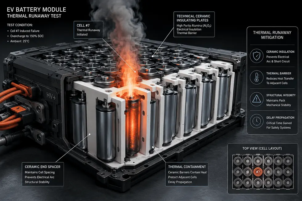
Why ceramic insulation is used to contain EV battery thermal runaway
Ceramic insulation is used inside EV battery packs because it stays dielectric and dimensionally stable at temperatures where polymer separators and structural plastics soften, shrink, or melt. Standard polyolefin separators shrink near 130°C and fail by 150°C, while a single lithium-ion cell in thermal runaway has been reported to reach roughly 800°C — a gap only inorganic materials like ceramic and mica reliably span.
This matters because a battery pack does two separate jobs at once during a fault: it has to keep the failing cell electrically isolated from its neighbors, and it has to keep those neighbors physically spaced apart so heat doesn't jump the gap. Polymer brackets and separators can do both jobs at normal operating temperature, but they lose mechanical integrity — and with it, spacing and isolation — well before a runaway event peaks. Ceramic components (and, in thinner applications, ceramic-coated separator films) are specified specifically to hold their shape and dielectric properties through that window.
This doesn't mean every ceramic grade behaves the same way at high temperature, or that ceramic insulation alone prevents a thermal event — it's one layer in a pack-level safety design that also includes the battery management system, venting, and enclosure. In practical terms, ceramic components are typically specified wherever a design needs to survive temperatures above the polymer failure window without losing electrical isolation.
Alumina, aluminum nitride, and zirconia: How the three ceramics compare for battery insulation
Alumina, aluminum nitride, and zirconia are all electrical insulators, but they manage heat very differently. 96% alumina conducts heat at roughly 20 W/(m·K); aluminum nitride conducts 170–230 W/(m·K), roughly an order of magnitude higher; yttria-stabilized zirconia conducts only about 2–3 W/(m·K). The right choice depends on whether a design needs to spread heat away from a hot spot or hold it back from spreading further.
Material / grade | Thermal conductivity | Volume resistivity | Dielectric strength | Design role |
96% Alumina (Al₂O₃) | ~20 W/(m·K) at 20°C¹ | ~1×10¹⁵ Ω·cm at 25°C¹ | ~17 kV/mm at 3 mm¹ | Moderate-conductivity dielectric barrier; general-purpose cell/case isolation |
Aluminum nitride (AlN), standard grade | 170–180 W/(m·K); ultra-high-purity grades to ~220–230 W/(m·K)² | >1×10¹³ Ω·cm at RT³ | ~10 kV/mm³ | High-conductivity — spreads heat away from a hot spot (busbars, terminals) |
Zirconia (YSZ, standard/3 mol) | ~2.0–3.0 W/(m·K)⁴ | >1×10¹³ Ω·cm⁴ | ~33 kV/mm⁴ | Low-conductivity — holds heat back rather than spreading it; higher fracture toughness for structural standoffs |
Sources: ¹Ceramaret 96% alumina datasheet. ²Precision Ceramics USA thermal-conductivity data. ³MSE Supplies AlN substrate datasheet. ⁴Precise Ceramic / Heeger Materials zirconia property data.
Continuous-use temperature ceilings for MAC's specific alumina, AlN, and zirconia grades are not included above; request a grade-specific datasheet for your application's operating range.
These figures are typical values from named manufacturer and materials-reference sources, not MAC's own tested output for these exact grades. Values vary with purity, sintering route, and thickness, so treat the table as a starting point for material selection, not a substitute for a grade-specific datasheet. From an engineering perspective, thermal-conductivity direction — not insulation resistance alone — is usually the deciding factor between these three materials.

How ceramic insulation compares to mica and polymer separators on temperature limits
Standard polyolefin (PP/PE) separator film shrinks near 130°C and melts by 150°C or above (ScienceDirect, 2020); PPS engineering plastic — used in structural insulators, not thin separators — holds up long-term to 200–240°C, short-term to 260°C, with an autoignition point near 290°C (NCBI/PMC, 2025); mica sheet is reported in industry and patent literature to maintain insulation resistance into the 500–1000°C range. Ceramics as a class sit at or above the mica range while adding rigidity mica doesn't have.
Temperature ceiling isn't the only variable. Mica is comparatively low-cost and widely used for exactly this reason, but it typically needs thicker, heavier layers to hit the same fire-protection performance as a thinner ceramic sheet, and it doesn't hold a shape the way a rigid ceramic spacer does. That rigidity is part of why ceramic spacers are also used to keep cell-to-cell spacing fixed during a mechanical or thermal event — bracket or spacer materials that soften or melt let cells drift closer together, which shortens the time before a fault propagates.
None of this means ceramic is the default right answer for every location in a pack — where flexibility, formability around irregular geometry, or lowest possible cost matters more than rigidity, mica or a fire-protection polymer may be the better fit. For procurement purposes, temperature ceiling is one input among several — weight, thickness, and mechanical rigidity budgets typically decide the final call.
Where ceramic insulation components are used inside an EV or ESS battery pack
Ceramic insulation components typically appear in four locations in a pack: cell-to-cell separators or spacers, module-to-module barriers, busbar and terminal standoffs, and cell-to-case liners. Each location does a different job — dielectric isolation, heat routing, or physically holding spacing — and the material choice in Section 2 above follows from which job dominates at that location.

Pack-level test frameworks such as GB 38031-2025 (which requires no fire or explosion for at least 120 minutes after a triggered thermal-runaway event) and the UL 2580 / SAE J2464 / GB 38031 family of thermal-propagation standards are what drive these placements — a pack has to demonstrate it can hold isolation and spacing under a defined abuse scenario, not just under normal operation. It's worth being precise about what that means for a ceramic component: these standards certify the finished pack or system, not an individual ceramic part on its own. A ceramic spacer contributes to a pack passing GB 38031 or UL 2580 testing; it isn't itself "UL 2580 certified."
In practical terms, the ceramic component's job is to hold its shape and its electrical isolation long enough for the pack-level system — BMS, venting, and enclosure — to do the rest.
How to specify ceramic insulation thickness and dielectric rating on a battery-pack drawing
Minimum insulation thickness is set by dividing the maximum system voltage a barrier must withstand by the material's dielectric strength, then applying a safety factor — industry practice commonly uses 2× to 3× — to account for manufacturing tolerance and aging. This is a physics-based calculation specific to each application, not a fixed thickness rule of thumb.
Concretely: if your pack's maximum surge voltage is V and the ceramic grade's dielectric strength is D (kV/mm), the baseline thickness is V ÷ D; multiplying that by a 2–3× safety factor gives a practical design thickness. Dielectric strength is commonly reported to decline somewhat at elevated temperature relative to room-temperature datasheet values, so the calculation should use the material's rating at your actual operating temperature where that data is available, not just the room-temperature number in a datasheet.
This calculation gets you to a starting thickness, not a final one — it still needs to be checked against space, weight, and mechanical constraints on the actual drawing. For procurement purposes, a drawing with system voltage, safety factor, and target thickness gives us everything we need to quote and confirm dielectric margin against your specific application.
Sourcing custom ceramic insulation components for EV and ESS battery programs
Microns Advanced Ceramics designs and machines custom ceramic insulation components — alumina, aluminum nitride, zirconia, and other technical ceramics — for EV and ESS battery programs, combining US-based engineering and application support with factory-direct global manufacturing. Drawing-based quoting is available directly through our RFQ process.
Send us a CAD file or drawing with your target dielectric rating, thickness, and operating-temperature range, and our engineering team will review it for feasibility and fit before quoting — this is the fastest path to a firm price and lead time. MAC's stated goal is to respond to drawing and RFQ submissions within one business day; inspection reports are provided with production runs, and a sample report is available on request for your specific grade and process.
On sourcing: because MAC's global manufacturing runs through a factory-direct model, landed cost is affected by US tariff policy on ceramic imports — a policy that has changed more than once in recent months. Rather than quote a fixed percentage that may already be out of date by the time you read this, we calculate landed cost at quote time against current duty schedules for your specific component. In practical terms, the fastest way to get a firm price and lead time is to send your drawing with target dielectric and thickness values for engineering review.
FAQ
Does ceramic insulation add significant weight to an EV battery pack?
Ceramic insulation is generally denser than aerogel or foam alternatives but can be thinner for the same dielectric rating; net pack weight depends on the specific thickness, coverage area, and grade selected, so it should be evaluated against the full material stack rather than judged in isolation.
How thick does ceramic insulation need to be for cell-to-cell separation?
Thickness is set by dividing the maximum system voltage a barrier must withstand by the chosen grade's dielectric strength, then applying an industry-standard safety factor of roughly 2× to 3×; exact thickness should be calculated per application rather than assumed from a general rule of thumb.
Can ceramic components help a battery pack pass GB 38031 or UL 2580 thermal-propagation testing?
Ceramic components can contribute to pack-level thermal-propagation performance by maintaining dielectric isolation and cell spacing at temperatures where polymer alternatives fail, but GB 38031 and UL 2580 certify the finished pack or system — not an individual ceramic component in isolation.
Is ceramic insulation reusable after a thermal event, or does the whole module need replacement?
Ceramic insulation is chemically and dimensionally stable through a thermal event and doesn't itself require replacement due to melting or off-gassing; standard practice, however, is to replace the affected cell, module, and any structurally compromised components as part of pack-level repair, regardless of insulation material.


Comments