


Preventing Thermal Runaway Propagation in Battery Packs
- Sibtain Haider
- 15 minutes ago
- 9 min read

How to Prevent Thermal Runaway Propagation in a Battery Pack
Preventing thermal runaway propagation means stopping heat from one failing lithium-ion cell from pushing its neighbors past their own failure point. It combines cell-level design, pack-level thermal isolation, and materials — ceramic, aerogel, mica, or composite — chosen for low conductivity and high-temperature survivability, evaluated against standards including GB 38031, UL 9540A, UL 2580, and UL 2596.
Why a single cell failure can cascade through an entire battery pack
A failing lithium-ion cell can exceed 800°C during runaway, and thermal runaway propagation (TRP) is the cell-to-cell chain reaction in which that heat pushes adjacent cells into failure in turn, escalating a single-cell event into a module- or pack-wide one within minutes. It is triggered by internal short circuits, mechanical damage, overcharge, or manufacturing defects, and once started it is largely a heat-transfer and containment problem rather than a chemistry problem.
Cells in a module sit close together for energy density, which is exactly what makes propagation possible: the mechanisms behind thermal runaway span mechanical, electrical, and thermal abuse, but the propagation step itself is governed by how much of the failing cell's heat actually reaches its neighbors. Reduce that heat transfer — by insulating, redirecting, or absorbing it — and the chain reaction can be slowed or stopped before it reaches the next cell.
This is a design problem with real engineering trade-offs, not a single material swap: a barrier that blocks heat perfectly but adds too much mass or thickness will fail on packaging and range targets before it ever gets tested for safety.
In practical terms, propagation containment is what turns "one bad cell" into a contained, survivable event instead of a pack-level fire — and it's the specific behavior every relevant standard is now built to test.
What GB 38031, UL 9540A, UL 2580, and UL 2596 require
China's GB 38031 mandates no fire or explosion for at least 5 minutes after single-cell thermal runaway (2020 edition) or 2 hours (2025 edition, phasing in from July 2026). In the US, UL 9540A tests propagation in battery energy storage systems, UL 2580 covers EV battery system safety broadly, and UL 2596 specifically tests the thermal and mechanical performance of battery enclosure/barrier materials.
Four standards govern most propagation-containment work a US-based ceramics supplier will see cited in an RFP:
Standard. | Scope | Core propagation requirement | Source |
GB 38031-2020 | China, mandatory EV traction batteries | No danger to the passenger compartment within 5 minutes of single-cell thermal runaway, with a thermal-event alarm issued in that window. | |
GB 38031-2025 | China, mandatory, new models from July 1, 2026 | No fire or explosion for at least 120 minutes after a severe internal defect, alarm still within 5 minutes, no visible smoke to the cabin, Southwest Research Institute plus a new bottom-impact test using a 30 mm steel ball at 150 J | IDTechEx / batterydesign.net |
UL 9540A (5th ed., 2025) | US/Canada, battery energy storage systems | Assesses fire propagation from thermal runaway; the only consensus standard cited in UL 9540A standard for large-scale fire testing, ACE Battery run across four escalating levels — cell, module, unit, and installation | UL Solutions / EticaAG |
UL 2580 | US, EV battery systems | Standard for Batteries for Use in Electric Vehicles, GlobalSpec covering thermal, mechanical, and electrical abuse at the pack level via UL Solutions testing services | UL Solutions |
UL 2596 | US, battery enclosure/barrier materials | Test method for the thermal and mechanical performance of the barrier materials themselves, rather than the whole pack | GlobalSpec |

The distinction that trips up a lot of sourcing decisions: UL 9540A and GB 38031 test the pack or system's behavior during a runaway event; UL 2596 tests the barrier material in isolation. A component supplier's data sheet can speak to UL 2596-relevant material properties (conductivity, temperature survivability); it cannot by itself claim pack-level GB 38031 or UL 9540A compliance, because that depends on the full system design.
For procurement purposes, the standard your customer cites tells you what level of the pack you're actually being asked to help qualify — material, module, or full system — and that should shape what a supplier is asked to warrant in a quote.
How rigid technical ceramics compare to engineered composite thermal barriers
Rigid technical ceramics (alumina, zirconia, silicon nitride) offer high-temperature stability and electrical isolation, but their thermal conductivity — roughly 2 to 35 W/m·K depending on material and grade — is far higher than purpose-built composite thermal barriers (aerogel, mica-based), which run in the 0.05–0.2 W/m·K range. The two material classes solve different parts of the propagation problem.
Material class | Representative grade | Thermal conductivity | Flexural strength | Fracture toughness | Continuous-use temperature | Named source |
Alumina (rigid oxide ceramic) | 99.5% Al₂O₃ | 35 W/m·K | 379 MPa | 4 MPa·m^0.5 | ~1750°C (no load) | Accuratus datasheet, corroborated by materialref.com citing CeramTec/Kyocera/CoorsTek |
Zirconia (rigid oxide ceramic) | 3Y-TZP | ~2.2 W/m·K | ~1000 MPa | 5–11 MPa·m^0.5 (grade/method-dependent) | ~1000–1330°C structural maximum | CoorsTek YTZP datasheet |
Silicon nitride (rigid non-oxide ceramic) | SRBSN vs. HIP-dense grade | 28–29 W/m·K | 689 MPa (SRBSN) to 850 MPa (dense HIP grade) | 5.7–8.5 MPa·m^0.5 | 1100–1400°C, grade-dependent | Accuratus; Precision Ceramics datasheets |
Engineered composite barrier (general reference, not a MAC product) | Aerogel/mica-type composite | 0.05–0.2 W/m·K, rated to survive brief exposure above 800°C | Flexible, non-structural | Not applicable | Event-rated, not continuous-service-rated | US patent literature (battery enclosure thermal barrier design) |
Two things follow from this table. First, among rigid ceramics, zirconia is the closer fit to "thermal barrier" behavior — its conductivity is roughly an order of magnitude lower than alumina's or silicon nitride's, which matters when the design goal is slowing heat transfer rather than spreading it. Second, no rigid ceramic gets close to the conductivity of a purpose-built composite barrier; that gap is real and worth designing around rather than talking around.

Zirconia's low thermal conductivity comes with a caveat worth noting for aging predictions: its toughening mechanism relies on a stress-induced phase transformation that also governs low-temperature degradation (LTD) in humid, moderately warm service conditions — a documented flexural-strength drop after aging appears in the peer-reviewed literature, so any zirconia specification for a battery-pack environment should account for the specific service temperature and humidity profile, not just room-temperature data.
From an engineering perspective, rigid ceramics and engineered composite barriers aren't competing solutions to the same problem — ceramics contribute structural isolation and electrical insulation at the interface, while composite barriers contribute the low-conductivity heat block itself, and most real containment architectures use both.
Where ceramic isolation components fit in a propagation-containment architecture
Rigid ceramic components typically serve three functions inside a propagation-containment design: electrical isolation between high-voltage elements, structural separation that maintains barrier geometry under vibration and crash loads, and localized heat resistance at connection points and busbars — functions distinct from, and complementary to, a dedicated low-conductivity thermal barrier layer.
In a typical module or pack, that breaks down by location: at cell-to-cell interfaces, a low-conductivity material (composite barrier, or a thin rigid ceramic spacer where structural support also matters) limits direct heat transfer. At busbar and high-voltage interconnects, a rigid ceramic component — sleeve, bushing, or insulating plate — maintains electrical isolation at temperatures where polymer insulators have already degraded.
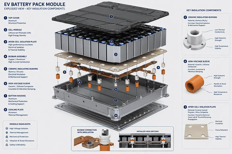
At module and pack boundaries, structural ceramic components can maintain a barrier's position and compression under the mechanical loads of vibration, thermal cycling, or a crash event, which matters because a barrier that has shifted or crushed out of place stops doing its job regardless of its intrinsic conductivity.
This functional split is why a bill of materials for a propagation-containment design commonly includes both a dedicated low-conductivity barrier layer and separate rigid-ceramic isolation components — they are addressing different failure modes, not competing for the same slot.
In practical terms, the question to ask isn't "ceramic or composite barrier" — it's which function, at which location in the pack, needs which property: conductivity, dielectric strength, or mechanical stability under load.
How to specify a ceramic inter-cell barrier for your battery program
Specifying a ceramic isolation component for a battery-safety program starts with the operating and event-case temperature range, the dielectric strength required at that temperature, the mechanical load and vibration profile, and the target standard (UL 9540A, UL 2580, GB 38031) the finished pack will be tested against — then a material and grade is chosen against those constraints, not the reverse.
Start with the failure case, not the normal operating case: a battery-pack ceramic component has to perform at both its everyday operating temperature and briefly at the runaway event temperature it's meant to help contain, and those two numbers can differ by hundreds of degrees. Specify dielectric strength at the actual operating temperature, since insulation performance for most ceramics is grade- and temperature-dependent rather than a flat number. Define the mechanical environment — vibration profile, crash-load direction, thermal-cycling count over the vehicle's service life — since a component that survives thermally but cracks or shifts mechanically has failed at its actual job. Identify which standard the finished pack is being qualified against, because that determines whether the component needs to be characterized on its own (UL 2596-style material testing) or only as part of a full pack-level test (UL 9540A, GB 38031, UL 2580).
A common misreading here is treating "high-temperature ceramic" as synonymous with "good thermal barrier" — a material can survive 1700°C and still conduct heat efficiently to the next cell, which is the opposite of what a barrier location needs. Match the property to the function (Section 4), not the material's headline temperature rating.
For procurement purposes, a specification built this way is one a supplier can actually quote against — a temperature range, a dielectric requirement, a mechanical load case, and a target standard, rather than a general request for "battery-safe ceramic."
Where MAC fits: US-based ceramic engineering versus dedicated barrier-material suppliers
MAC is not a manufacturer of engineered composite thermal-barrier materials — that category is led by specialists in aerogel and mica-based composites. MAC's role is supplying the rigid ceramic isolation components (alumina, zirconia, silicon nitride) described in Section 4, engineered and quality-managed from a US-based team, with manufacturing carried out through MAC's factory-direct global supply chain.
If you're searching for a "battery pack thermal barrier supplier," it's worth knowing there are two distinct categories of vendor behind that phrase. One category makes the low-conductivity composite barrier layer itself — companies like Aspen Aerogels, whose PyroThin barriers are in volume production with major automotive OEMs and which was named a 2025 GM Supplier of the Year for its role in GM's Ultium thermal-propagation strategy. The other category — where MAC sits — supplies the rigid ceramic components that handle electrical isolation and structural stability around that barrier, using materials whose properties are covered in Section 3. A program frequently sources from both categories rather than expecting one supplier to cover both roles.
Representative scenario (illustrative — not a specific client program). Consider a pack design using 3Y-TZP zirconia spacers at select cell-to-cell interfaces where structural support is also required, alongside alumina bushings isolating high-voltage busbar penetrations through the module wall. The zirconia's comparatively low conductivity (Section 3) contributes modestly to slowing conductive heat transfer at those interfaces, while its mechanical strength holds barrier geometry under vibration; the alumina bushings maintain dielectric isolation at busbar temperatures where polymer components would already have degraded. This is a description of how the material properties above map onto a plausible design, not a completed or measured program — MAC can work through the equivalent analysis for a specific design once cell format, voltage, and operating-temperature range are known.
MAC's part of this is US-based engineering, application support, and quality assurance, with manufacturing carried out through factory-direct global production — we do not market ourselves as a US manufacturer, and we won't claim a specific tolerance, certification, or test result on this page that we haven't confirmed in writing for the part in question. Inspection reports and material traceability are available on request; run this design question directly through our engineering team, including a drawing upload, at Request an RFQ. If you're earlier in materials selection, our lithium battery ceramic components page covers the current product range.
FAQ
What temperature can a lithium-ion cell reach during thermal runaway? Cell temperatures during thermal runaway can exceed 800°C, which is why insulating and structural materials chosen for propagation containment need to be evaluated at event-case temperatures, not just normal operating temperature.
Do ceramic components alone stop thermal runaway propagation? Not on their own in most designs. Rigid ceramics contribute electrical isolation and structural stability at specific interfaces, while the primary low-conductivity heat block is typically provided by a dedicated composite barrier material — the two usually work together rather than one replacing the other.
What's the difference between UL 9540A and UL 2596? UL 9540A evaluates fire propagation at the system level in battery energy storage systems, while UL 2596 tests the thermal and mechanical performance of the barrier material itself — one is a pack-level test, the other a material-level test.
Is MAC a thermal-barrier material supplier? No. MAC engineers and supplies rigid ceramic components — alumina, zirconia, silicon nitride, and related materials — used for electrical isolation and structural stability inside a propagation-containment design; the low-conductivity composite barrier layer itself is typically sourced from a specialist in that material category.
Can MAC support a program being qualified to GB 38031, UL 9540A, or UL 2580? MAC can supply and characterize the rigid ceramic components used within such a program from a US-based engineering team with factory-direct manufacturing; pack-level qualification against those standards depends on the full system design and is validated by the customer's own test program.


Comments